Three-dimensional (3D) printing refers to all the processes used to generate a product by superim- posing layers of material based on a 3-dimensional digital model. The term “3D printing” is most commonly used in the “general public” field, whereas the term “Additive Manufacturing (AF)” is most commonly used by professionals, i.e. in industrial applications.
This manufacturing process differs greatly from the usual techniques for producing parts. Additive manufacturing proceeds by adding material while machining proceeds by removing material. Therefore, no specific tool is required for 3D printing (cutting tool or mould, for example).
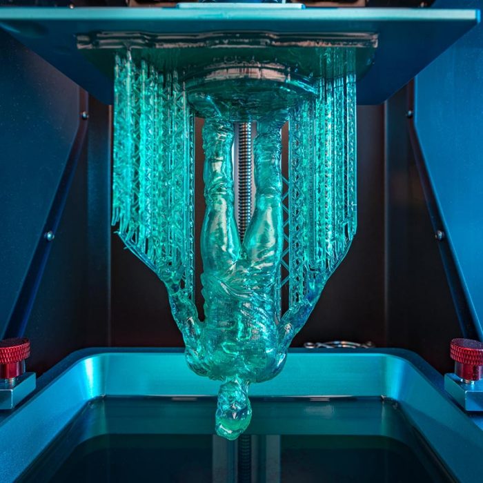
A Stereolithography Apparatus (SLA), solidifies a photosensitive liquid polymer (which can be called “photopolymer”) using an ultraviolet laser beam. SLA printers consist of a reservoir of liquid photopolymer, a perforated platform, an ultraviolet emitter and a computer.
The Polyjet (material jet) process is also based on the principle of photopolymerisation. The photosensitive material is deposited drop by drop on a support and then exposed to an ultraviolet beam which instantly cures the resin. The advantage of this process is that it can print multi-material and coloured parts.
2 Solidification using light
A Stereolithography Apparatus (SLA), solidifies a photosensitive liquid polymer (which can be called “photopolymer”) using an ultraviolet laser beam. SLA printers consist of a reservoir of liquid photopolymer, a perforated platform, an ultraviolet emitter and a computer.
The Polyjet (material jet) process is also based on the principle of photopolymerisation. The photosensitive material is deposited drop by drop on a support and then exposed to an ultraviolet beam which instantly cures the resin. The advantage of this process is that it can print multi-material and coloured parts.
3 L’agglomération de poudre par collage
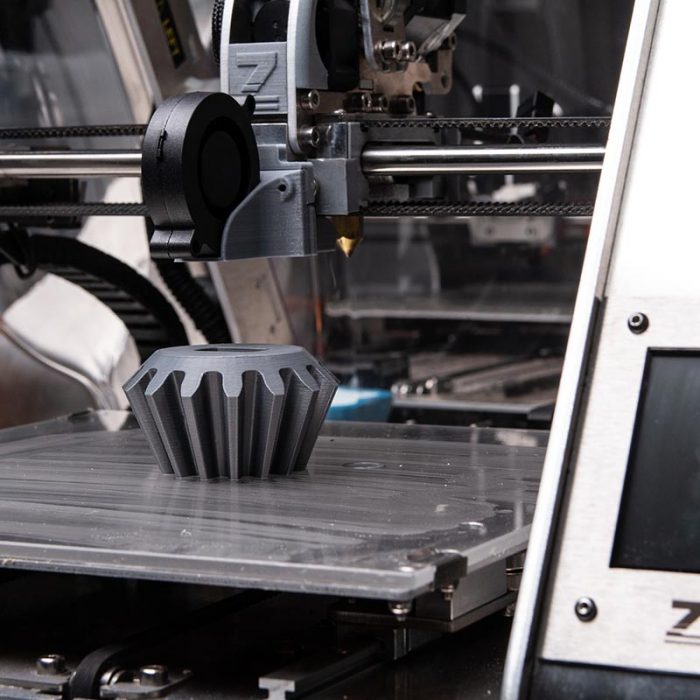
Three Dimensional Printing (3DP) uses fine drops of coloured glue to assemble fine particles of thin layers of composites spread on a platform. This platform is lowered as the layers are made until the final part is obtained.
The processes mentioned above are adapted and developed mainly for the printing of polymer parts. Nevertheless, additive metal manufacturing has been gained momentum in recent years and has undergone numerous technological developments. These advances allow more and more innovative manufacturing methods and generate a wider range of usable materials. Among the additive metal manufacturing processes we find mainly:
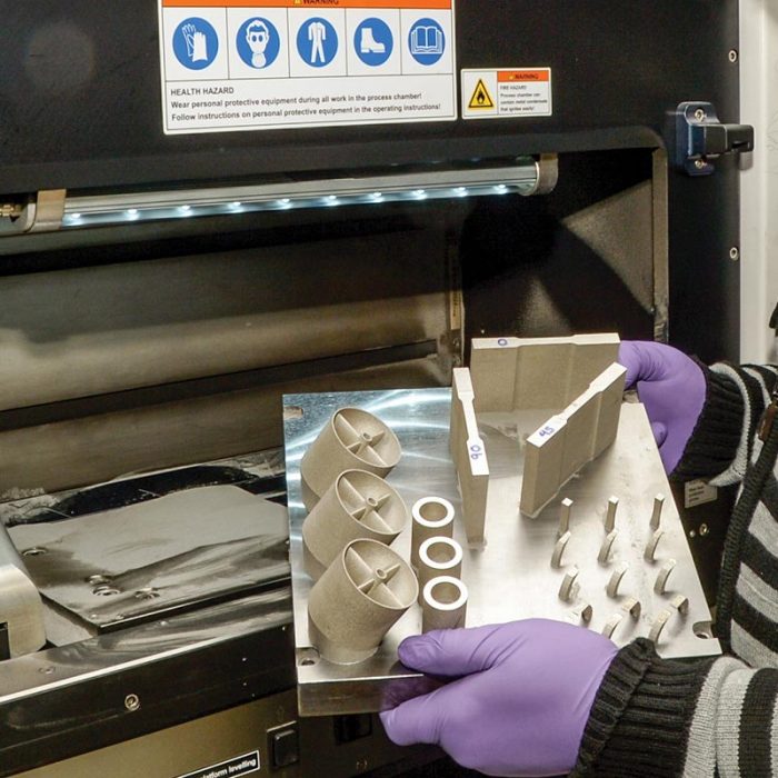
Direct Metal Laser Sintering (DMLS), part of the 3D printing family called “powder bed fusion”. This method is based on the same principle as the SLS process, i.e. precise heating by means of a laser beam to sinter or fuse metal powder particles together and thus produce the final part layer by layer.
Direct Laser Additive Construction (DLAC): concentrated energy material deposition technology. It consists of feeding material in the form of metal powder or wire through the printer nozzle and immediately melting it at the outlet using a powerful heat source: in this case a laser beam (other technologies exist for which heating is provided by an electron beam – EBM – or plasma). This method allows direct printing of parts, unlike with the powder bed melting process.
Cold Spray: the aim is to coat a part by cold metallization. The metal powder particles are sprayed in a gas (nitrogen or helium) under pressure (approximately 50 bars) at very high speed (up to 1200m/s) onto the substrate. Upon impact, particle deformation ensures the quality of the deposit.
Stratoconception is a hybrid 3D printing process which breaks down the part to be produced into several layers. Each of the layers is created by some form of cutting (milling, laser cutting, wire sawing, etc.), which are then positioned using inserts, bridges or other nesting elements in order to be assembled and thus reconstitute the final part.
=> Various other technologies have been developed directly by some manufacturers. All these developments further distinguish the process categories already mentioned.
The field of 3D printing is a rapidly evolving one. It offers major advantages but also presents some limitations. The advantages include:
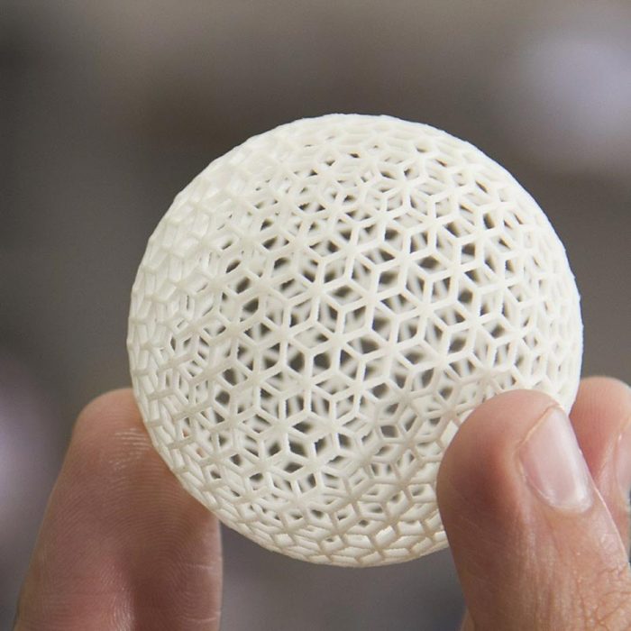
The ability to manufacture parts with complex geometries without increasing costs. The manufacturing process whereby layers are added makes it possible to achieve precise part geometries more easily than by “traditional” manufacturing, sometimes even at a lower cost because less material is used.
No specific tooling is required to create a product (as opposed to the tooling devices or moulds used in shapes manufacturing). The cost of a 3D printed part depends solely on the amount of material used, the time required to produce it and the subsequent processing operations.
The ease of creating customised parts. As start-up costs are low, each production can be personalised simply by modifying the 3D digital model.
Rapid prototyping at low cost. The rapidity of part manufacture greatly accelerates the “design cycle” (design, testing, improvement, modification, etc.).
The wide range of usable materials. Although the most commonly-used materials are plastics, metals and composites are finding more and more industrial applications to meet ever more specific needs.
Nevertheless, 3D printing in manufacturing presents some limitations:
For most 3D printing processes the physical properties of the products are not as good as those of the materials used. However, selective metal melting by laser processes (DMLS) do in some cases produce parts with excellent mechanical properties.
Additive manufacturing is limited by the number of products to be mass-produced. It cannot compete with other processes for very large production runs.
The tolerance and precision of parts are limited. They vary according to the printing process, but the parts often require finishing operations to optimise characteristics, tolerances and surface finishes. 3D-printed parts are rarely ready for use when they come off the “printer”. The finishing operations required are usually the removal of the substrate (i.e. all the printed structures to anchor the part and/or make up for imbalance during printing), sanding, polishing, painting, etc.
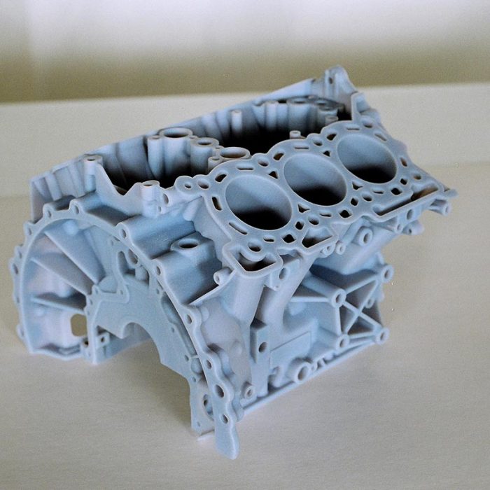
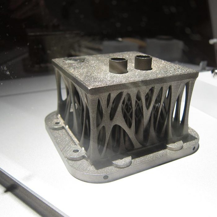
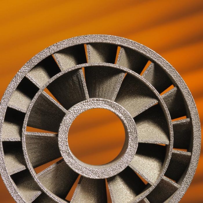
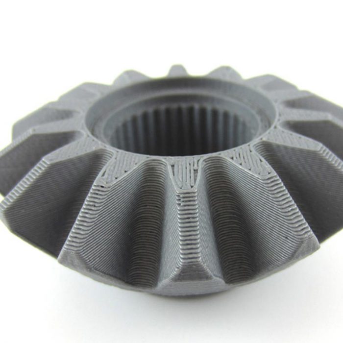
=> 3D printing is therefore used in many industrial fields. It finds applications in many activity sectors such as: automotive (titanium brake calliper), aeronautics (lightening of structures), naval aviation (ship propellers), energy (gas turbine blades), medical (titanium implants), aerospace (telescopic aluminium mirror, satellite antenna support, rocket engine turbo pump), metal construction (steel bridge), watchmaking, jewellery or goldsmith’s trade, etc.
It is the additive metal fabrication that will most often require metallographic preparation.
METALLOGRAPHIC PREPARATION
In general, depending on the printing technology, process, development, transformation operations and different finishing treatments, the properties and microstructures of the materials contained in the part are influenced.
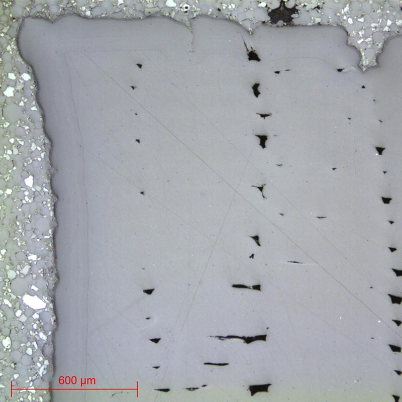
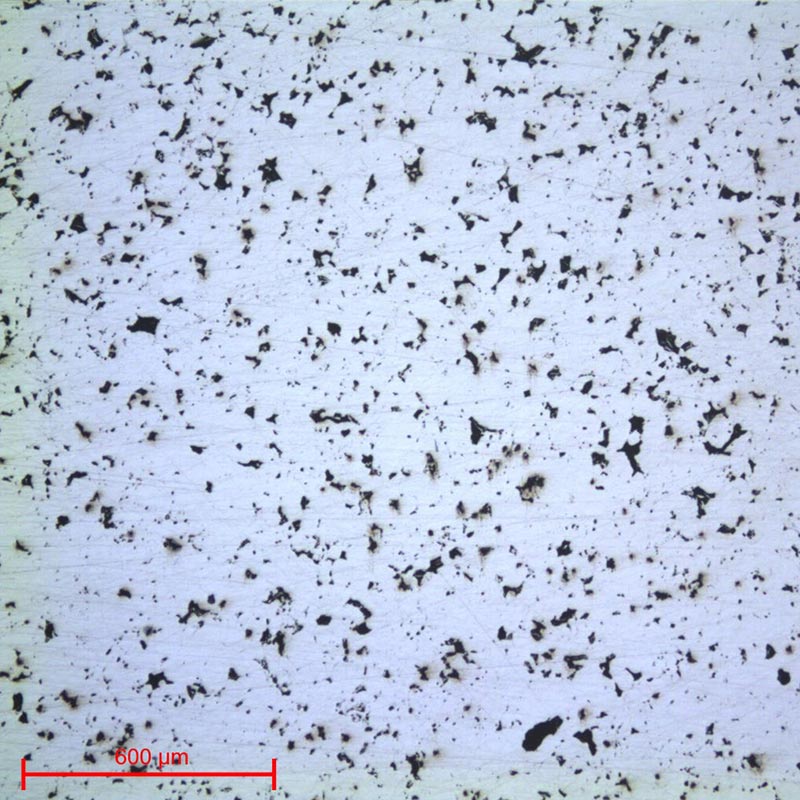
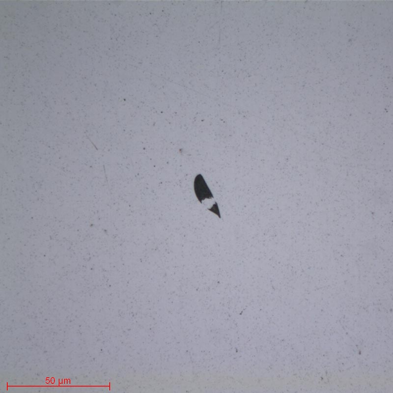
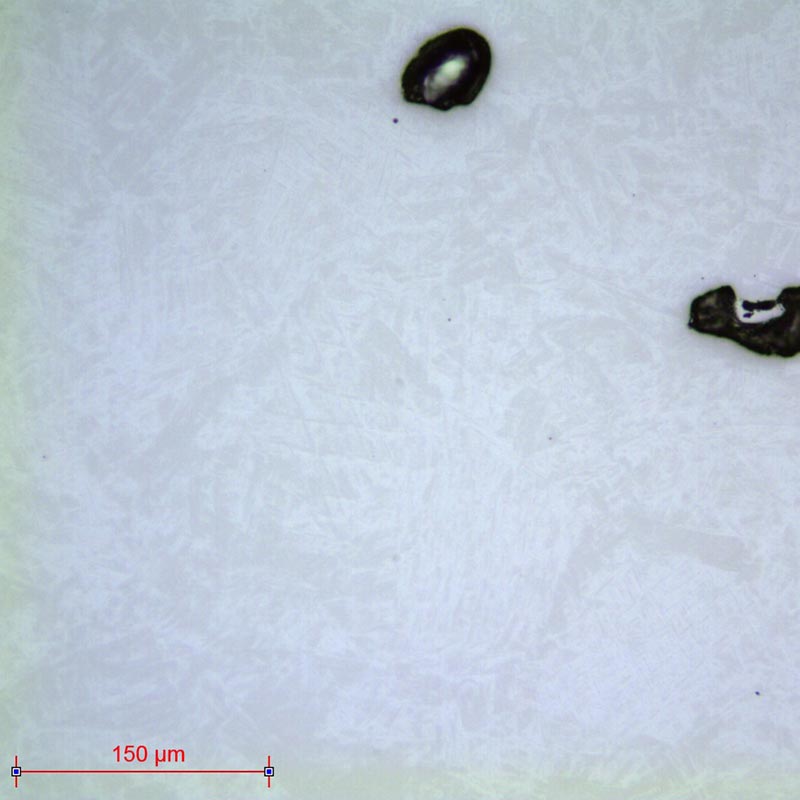
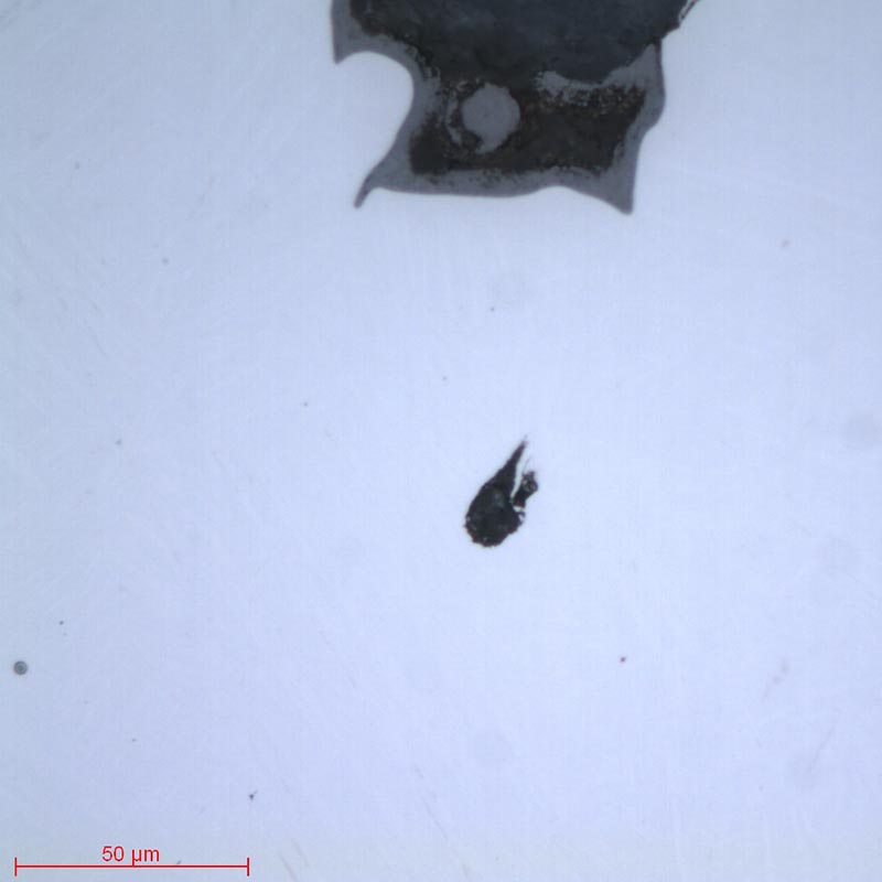
All these influences lead to metallographic quality controls such as: examinations of porosities, dimensioning, pull-out, structures and microstructures, searches for heterogeneities, search for and examination of inclusions and/or impurities, hardness tests, grain size controls, etc.
Obtaining an inspection surface requires a succession of operations, each as important as the next, regardless of the material. These steps are in the following order:
The removal of the product to be examined (if necessary), called “CUTTING”.
Standardisation of the geometry of the sample taken (if necessary), called “MOUNTING”.
Improvement of the surface condition of this sample, called “POLISHING”.
Characterisation of the sample: revealing the microstructure of the sample by an etching reagent (if necessary) called “METALLOGRAPHIC ETCHING” and microscopic observation (optical or electronic).
The purpose of cutting is to remove a precise section of a product, in order to obtain a suitable surface for inspection, without altering the physico-chemical properties of the materials in question. In other words, it is essential to avoid heating or any deformation of the metal that could lead to strain hardening. Cutting is a fundamental step which conditions the further preparation and inspection of parts.
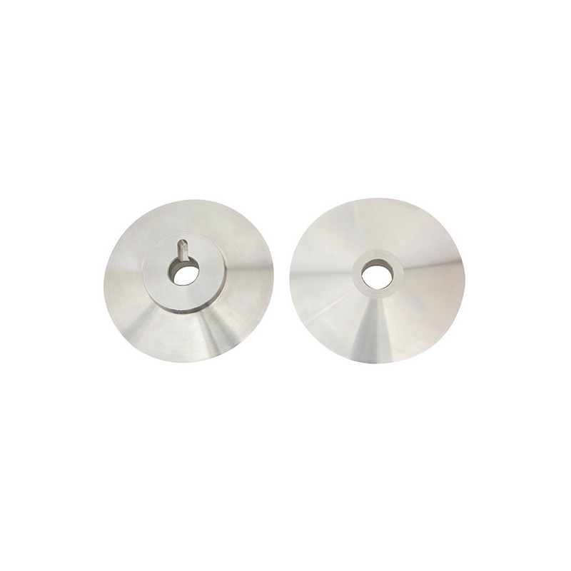
Each of the cutting machines in the range has its own customised consumables and accessories. The clamping system and choice of consumables are key factors in a successful metallographic cut.
=> Clamping, i.e. holding the workpiece, is essential. If the workpiece is not held properly, the cut can be detrimental to the cut-off wheel, the workpiece and the machine.
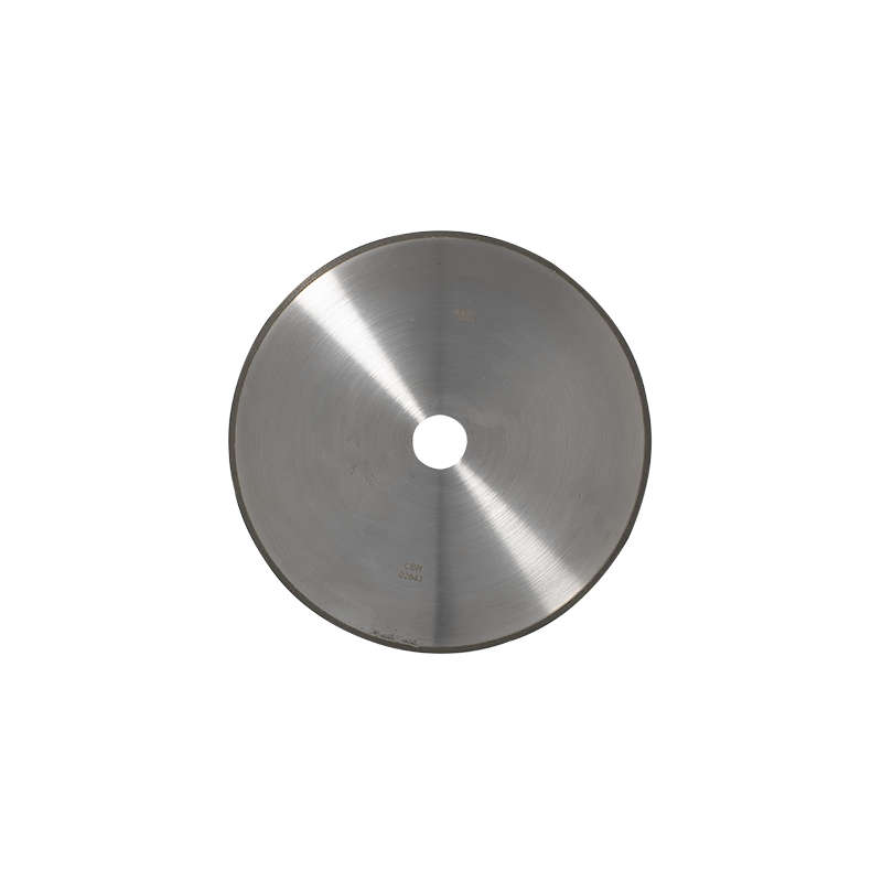
CONSUMABLES
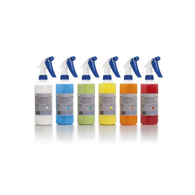
All cutting machines are used with a lubricating/cooling liquid composed of a mixture of water and anti-rust additive in order to obtain a clean cut without overheating. The additive also protects the sample and the machine from corrosion.
Polymer materials
Metallic materials
Céramic materials
Non-ferrous
Ferrous
Micro-cutting
UTW S Ø180 MNF LM+ LR
UTW S Ø180mm MNF
UTW S Ø180 A CBN
LM / LM+ LR
Medium-capacity cutting
MNF LM+ LR
T MNF F
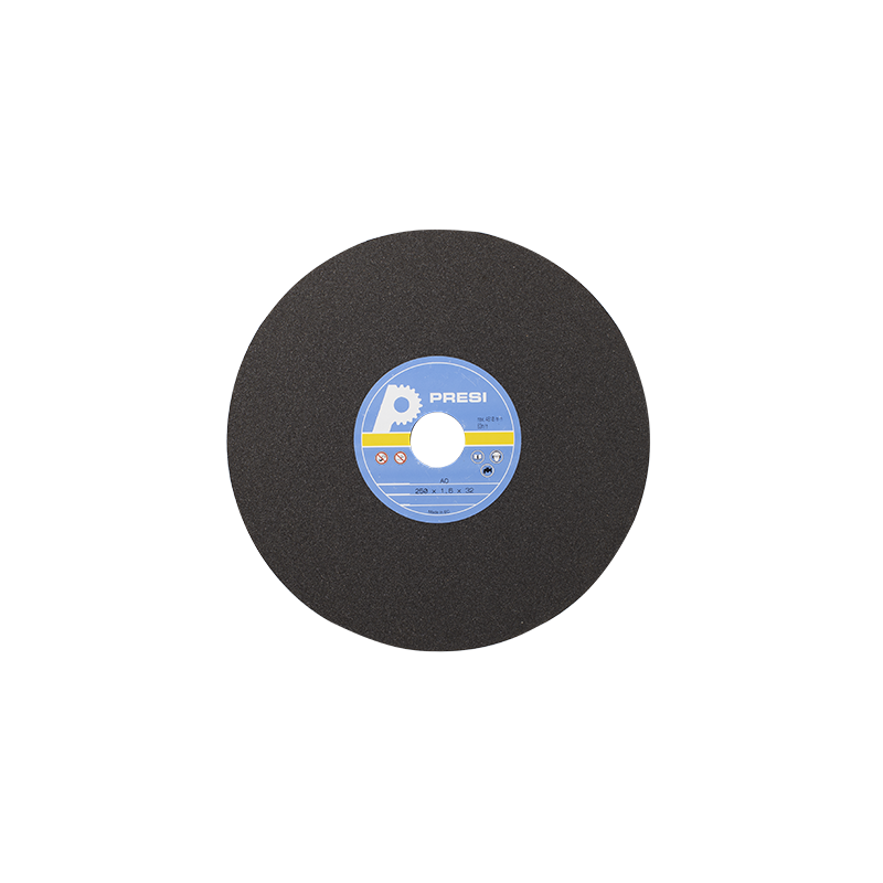
A AO S CBN
LM / LM+ LR
High-capacity cutting
MNF LM+ LR
T MNF
A AO S CBN
LM / LM+ LR
Table 1: Choosing the right cut-off wheel type
=> The choice of cut-off wheel type has to be adequate, in order to avoid cutting failure, or excessive cut-off wheel wear or even breakage.
Samples can be difficult to handle due to their complex shape, fragility or small size. Mounting makes them easier to handle by standardising their geometry and dimensions.
=> Achieving good-quality mounting is essential to protect fragile materials and also to achieve good preparation results for polishing and future analysis.
Before mounting, the specimen should be deburred with coarse abrasive paper, for example, to remove any cutting burrs. Cleaning with ethanol (in an ultrasonic tank for even greater efficiency) is also possible. This allows the resin to adhere as well as possible to the sample and thus limits shrinkage (space between the resin and the sample).
If shrinkage persists, it can lead to problems during polishing. Abrasive grains may become lodged in this space and then be released at a later stage, thus creating a risk of pollution for the sample and the polishing surface. In this case, cleaning with an ultrasonic cleaner between each step is recommended.
There are two mounting options:
HOT MOUNTING
He is to be preferred for edge inspection purposes or if the metallographic preparation is carried out in preparation for hardness testing. This option requires a hot-mounting machine.
The machine required for hot-mounting is the Mecapress 3:
Fully automatic hot-mounting press.
Easy to use: memorisation, adjustment of processes and speed of execution make it a high-precision machine,
The hot-mounting machine has 6 different mould diameters from 25.4-50mm.
+POINT
One of the main advantages of this process is that it provides perfectly parallel faces.
COLD MOUNTING
He is to be preferred:
If the parts to be examined are fragile/sensitive to pressure
If they have a complex geometry such as a honeycomb structure.
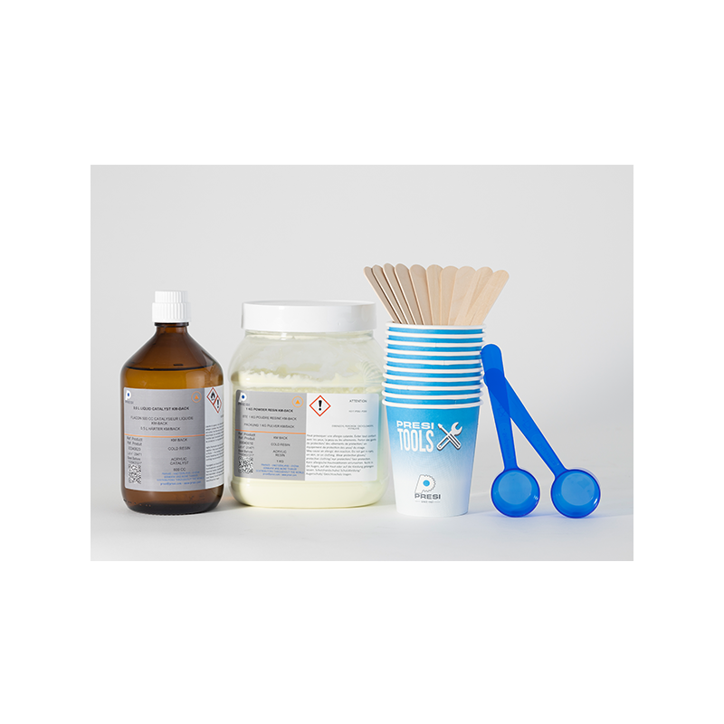
If a large number of parts are to be mounted in series. The cold process can be used with:
+POINT
Substantially improves quality, in particular by reducing shrinkage, optimising transparency and facilitating resin impregnation.
Cold resins do not always provide a flat mounting “back” because of the meniscus of the liquid resin. Before any polishing operation, a brief step using abrasive paper will remove this meniscus. The important thing is to ensure that this operation renders the two sides of the mounting parallel.
CONSUMABLES
To meet user needs, PRESI offers a full range of cold mounting moulds. The cold process has different mounting moulds with diameters from 20-50mm. These are divided into several types: optimised moulds called “KM2.0”, rubber, Teflon or polyethylene moulds. Cold mounting is also more flexible, hence the existence of rectangular moulds for more specific needs.
Polymer materials
Metallic materials
Ceramic materials
Hot process
Ø
Hot Epoxy Phenolic Allylic
Ø
Cold process
KM-U KM-B IP / IP-FAST MA2+
KM-U KM-B IP / IP-FAST 2S*
KM-U KM-B IP / IP-FAST
Tableau 2 : Choix du type de résine d’enrobage adapté
* Adaptée pour les très grandes séries
Ceramic and polymer materials are brittle and are sensitive to heat and/or pressure. It is therefore not recommended to perform a hot mounting process with this type of material.
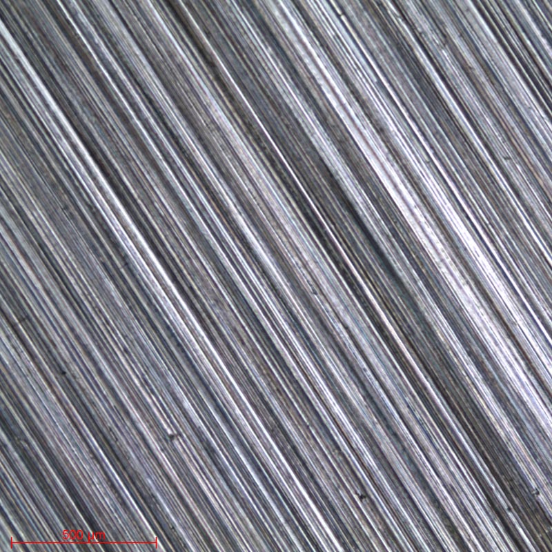
The last and crucial phase in the sample preparation process is polishing. The principle is simple, each step uses a finer abrasive than the previous one. The aim is to obtain a flat surface and to eliminate scratches and residual defects that would hinder the performance of metallographic control examinations such as microscopic analysis, hardness tests, microstructure or dimensional inspections.
The MINITECH range of manual polishers incorporates the most advanced technologies. User-friendly, reliable and robust, they provide a simple answer to all needs.
The MECATECH range of automatic polishers allows both manual and automatic polishing. With its advanced technologies, motor power from 750-1500 W, all the PRESI experience is concentrated in this very complete range. Whatever the sample number or size, MECATECH guarantees optimal polishing.
CONSUMABLES AND POLISHING RANGE
All the polishing ranges below are given for automatic sample preparation (for manual polishing: do not take into account the parameters at the top). They are the most commonly used and are given for information and advice.
All the first steps of each range are called “levelling” and consist of removing material quickly to level the surface of the sample (and resin). Those given below are standard and can therefore be modified as required.
Range
N°1
N°2
N°3
N°4
N°5
Material
Polymer materials
Steel and hard metals
Soft metals
Titanium
Ceramic materials
Table N°3: Choice of polishing range
RANGE N°1
N°
Support
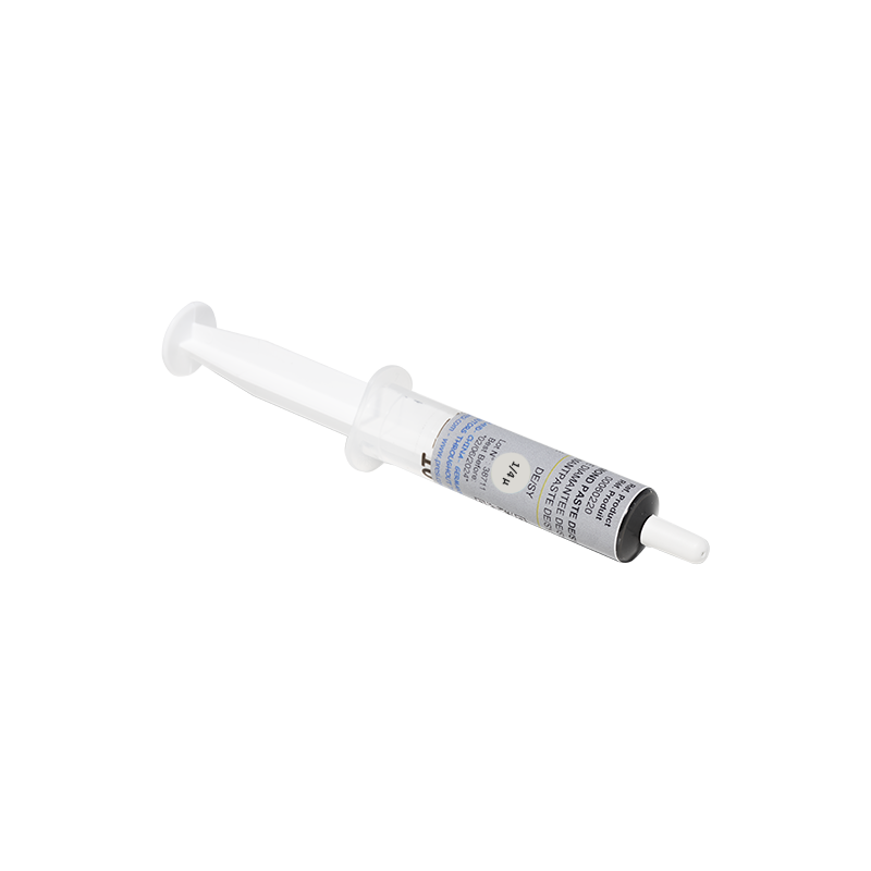
Suspension / lubricant
Platen Speed (RPM)
Head Speed (RPM)
Rotation direction plate / head
Time
1
SiC P600
Ø / Water
300
150
→ →
1’
2
TOP
9µm LDP / Reflex Lub
150
135
→ →
4’
3
STA
3µm LDP / Reflex Lub
150
135
→ →
3’
4
NT
Al2O3 n°1 / Water
150
100
→ ←
1’
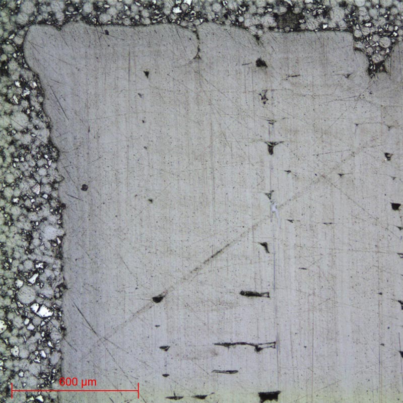
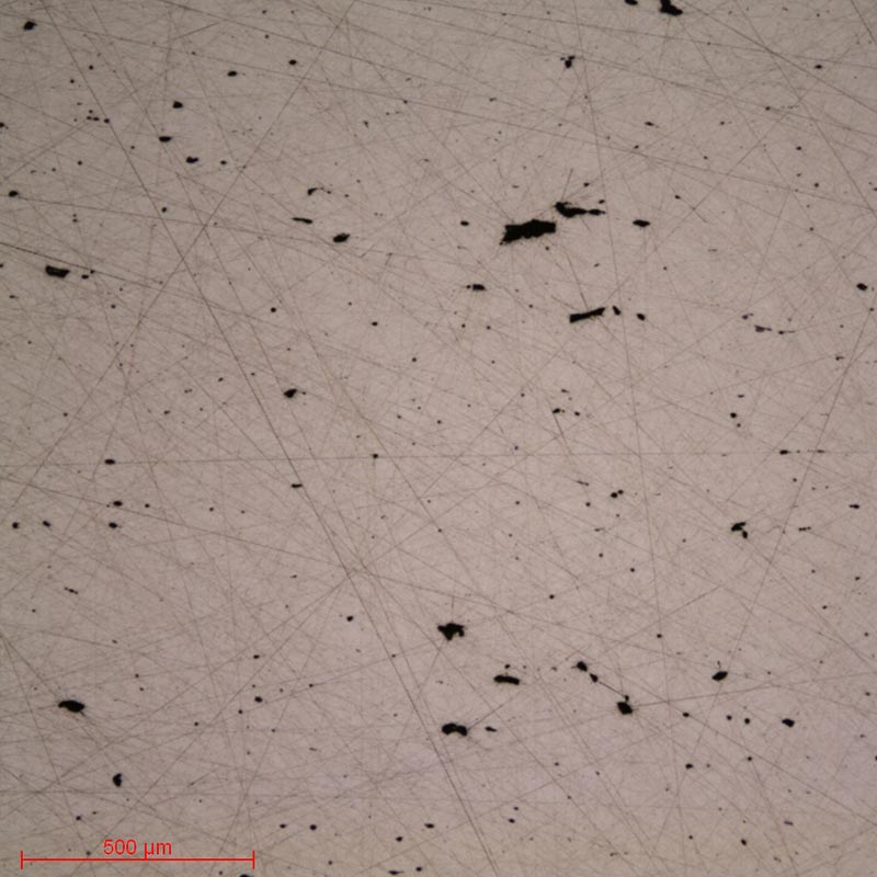
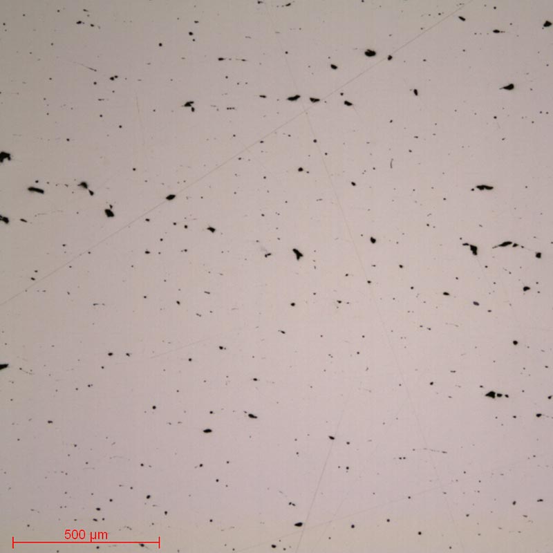
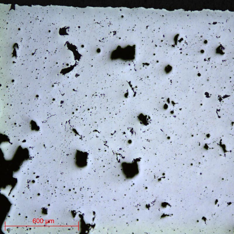
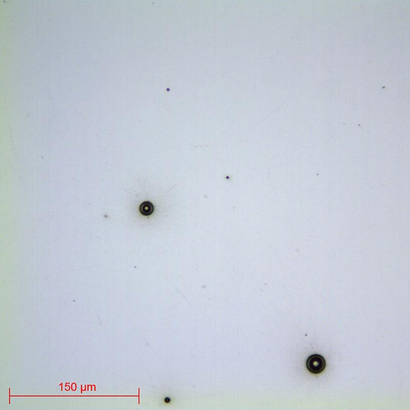
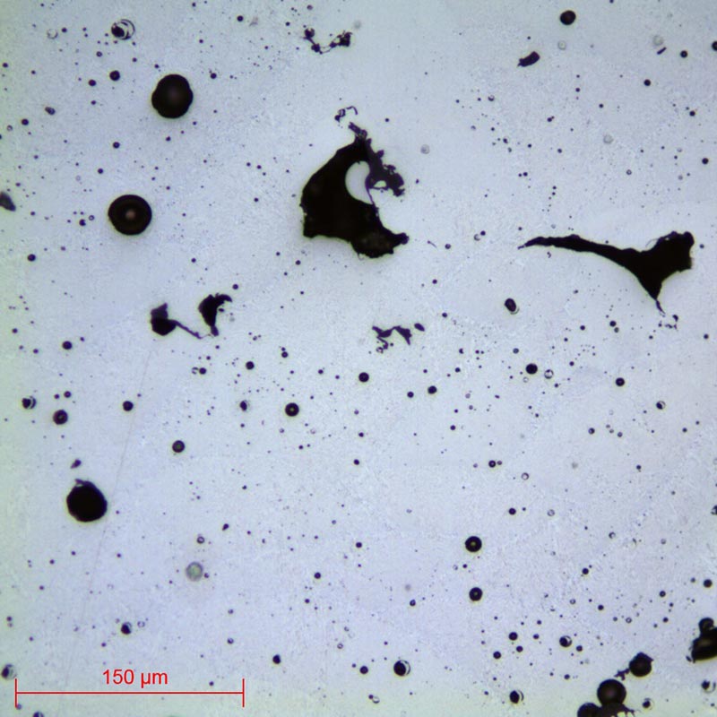
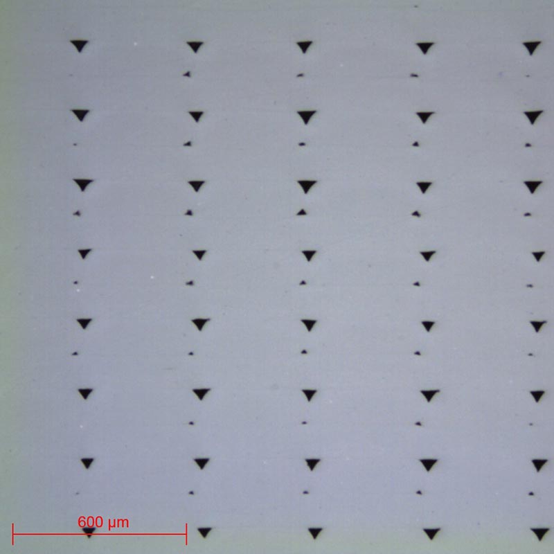
Micrograph 1: PLA – Surface condition TOP 9μm lens x5
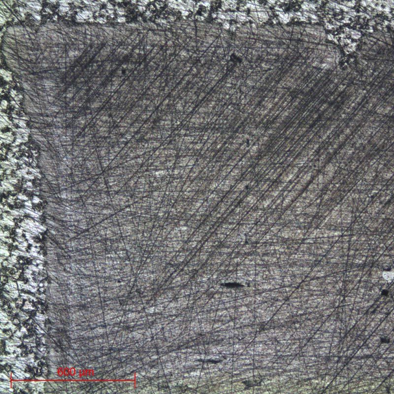
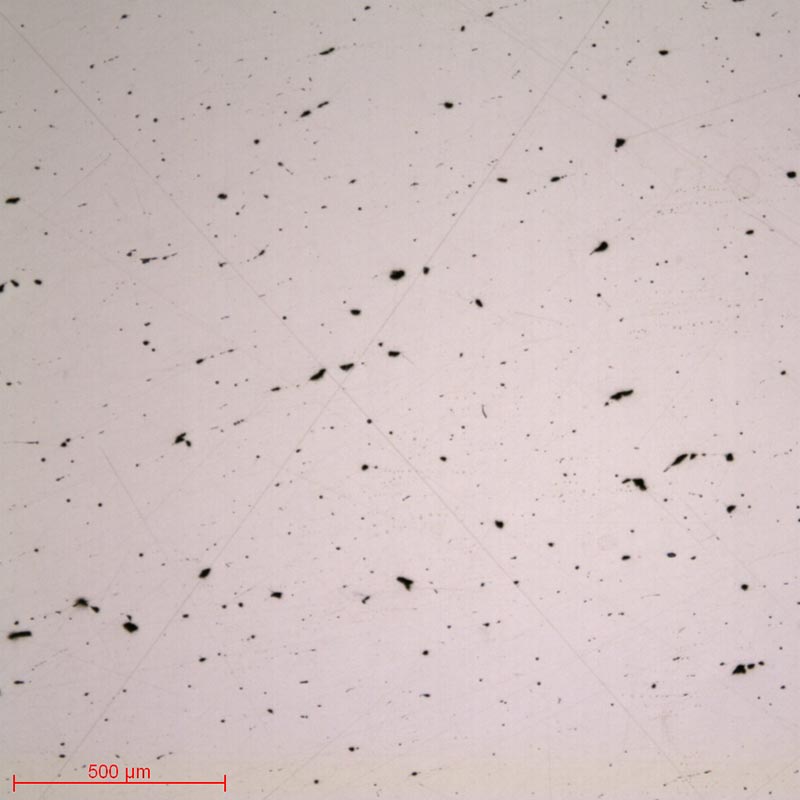
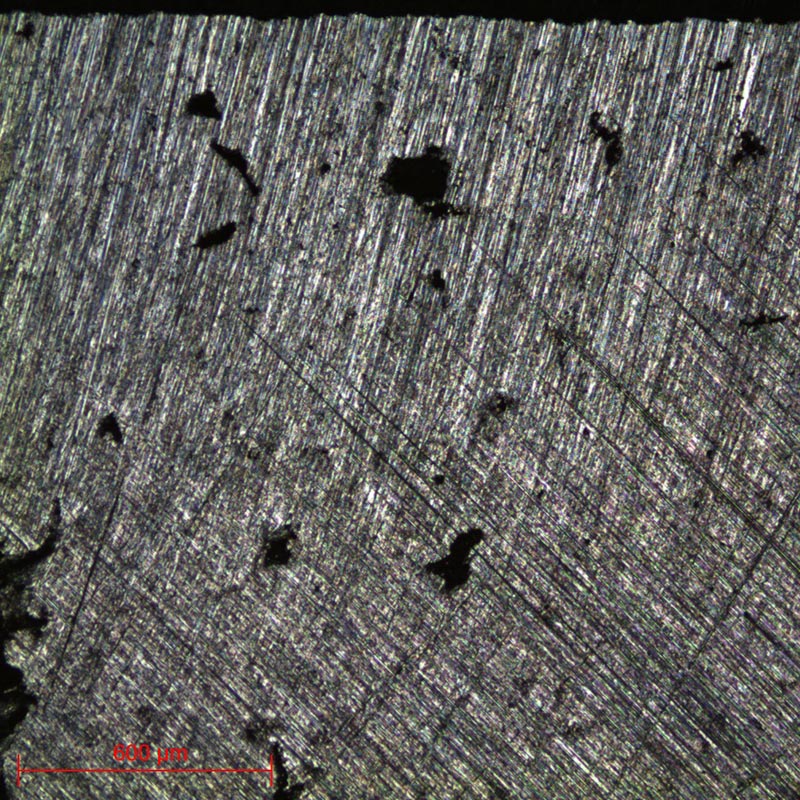
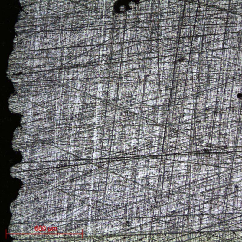
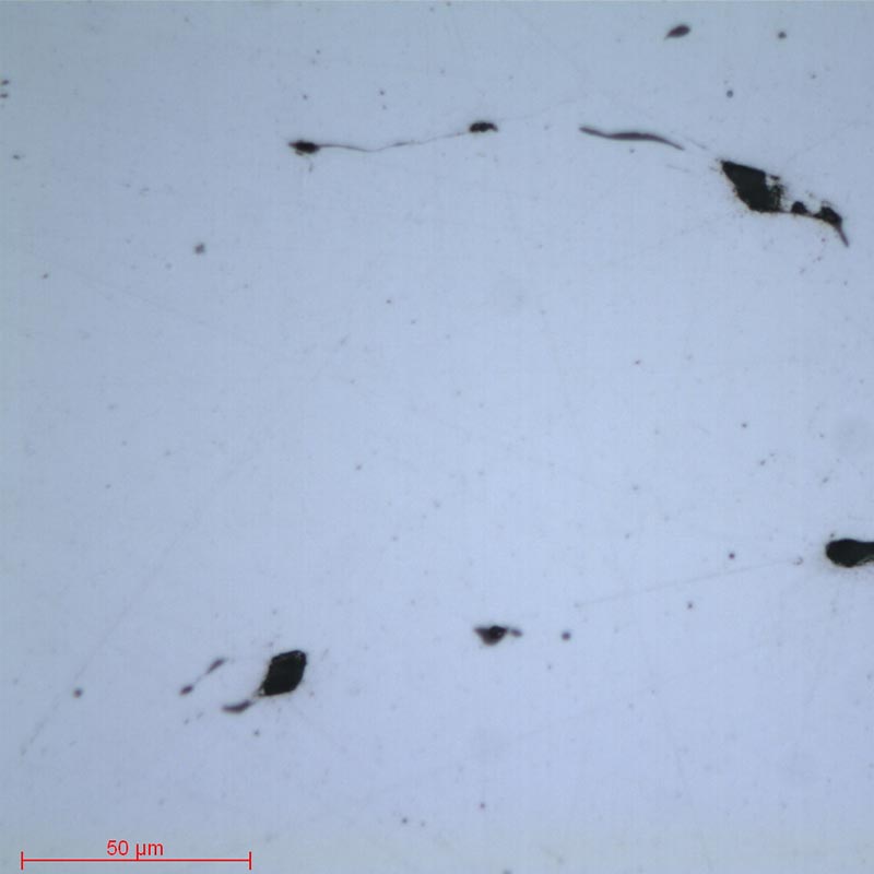
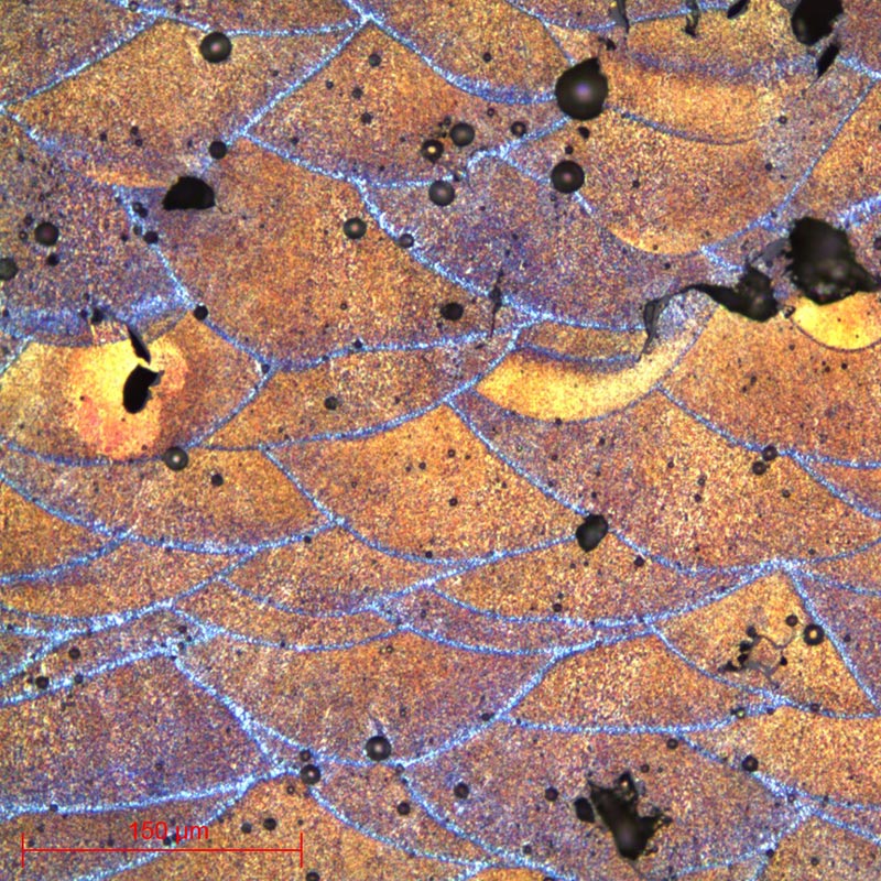
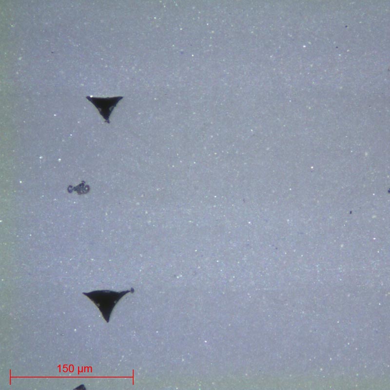
Micrograph 2: PLA – Surface condition STA 3μm lens x5
All the polishing ranges listed above are standard and versatile ranges that can be modified according to the subtleties of the samples.
Moreover, they are not necessarily to be carried out in their entirety; observations will define needs (except for titanium samples for which all the steps of the range must be performed).
At the end of this preparation phase, the polished samples can be directly observed without metallographic etching.